
USB endpoint housing
The case holds one Radxa ZERO 3E V1.2. R4 replaces the two rejected prints with a rectangular shell, a sliding joint and recessed M3 screws. It is a design candidate, not a released print. Physical fit and strength tests have not been run.
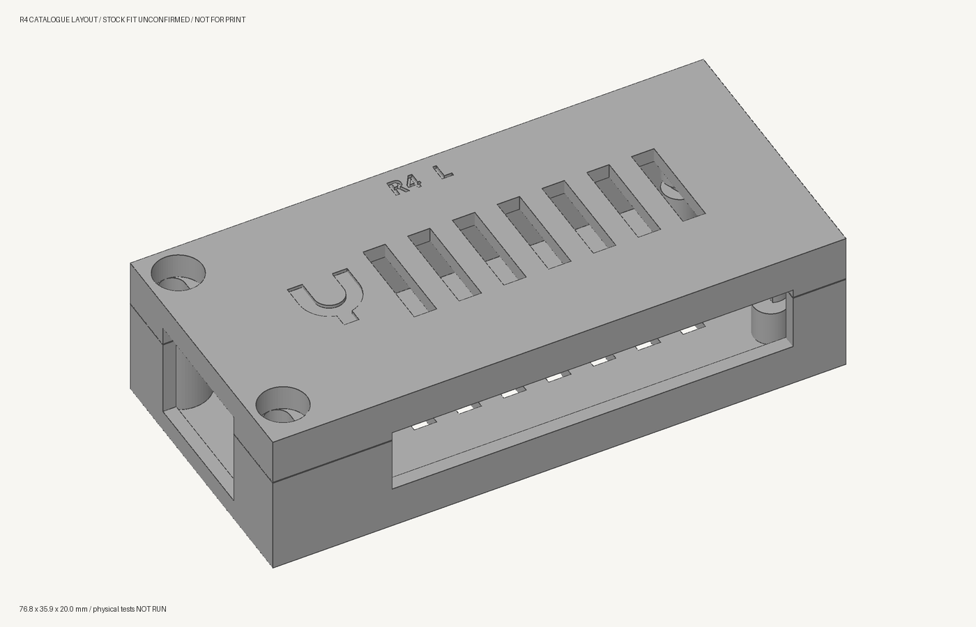
R4 assembly and test plan · Assembly drawings
R4: slots and screws
The lid lowers into locating slots, then slides into two retaining pockets at the back. Two screws at the Ethernet end hold it closed and prevent the slide from reversing. Opening reverses that sequence: remove both screws, slide the lid back, then lift it off.
The shell follows the loaded board's rectangular outline. Its fastener bosses stay inside the case; there are no projecting ears or turrets. The outer dimensions are 76.8 × 35.9 × 20 mm, including the shell around the Ethernet connector's overhang. The screws do not pass through the PCB. Internal pads support the board and two small locating pegs register it.
The hardware is the same type recorded in Lacuna's stock: M3 socket-head screws and RX M3×5.7 heat-set inserts. R4 uses two M3×8 screws, with recessed heads and clearance for a hex driver. Install the inserts in the empty base and let it cool before fitting the board.
The nominal insert profile comes from the Ruthex manufacturer datasheet: 4.6 mm outer diameter, 5.7 mm length and a 4.0 mm pilot hole. The actual stock still needs to be matched to that part. Printed-hole shrinkage, insert setting and screw fit need physical checks.
Before another full case print
The first R4 joint-test print was submitted and verified printing. It contains five small test pieces, uses an estimated 6.53 g of PLA and takes about 40 minutes. Use the separate joint assembly and test instructions after cooling. A started print does not establish that the joints fit.
Use the same Lacuna mesh, print-support and assembly-clearance tools, with the actual R4 geometry. Those checks can find unsupported features and modeled collisions. They cannot establish the fit of printed plastic, installed inserts or actual cables.
First qualify small samples of the actual joints: the front screw, insert and locating slot; then the rear tab and retaining pocket. Check screw engagement and head recess, the full slide movement, repeated opening and closing, and retention under a measured separating load. Only then prepare a complete case for print review. The full case also needs board, cable, Ethernet latch and thermal checks before use.
Rejected and earlier revisions
Do not print R1 or R3 again. The owner rejected both printed cases; the exact failure dimensions were not recorded. Their earlier digital approvals do not qualify R4 or establish that those assemblies worked. Lacuna's retired-job guard blocks the known rejected meshes and jobs.
| Revision | Status | Record |
|---|---|---|
| R3 | Printed; owner reported assembly failure | Owner result, historical assembly guide |
| R2 | Branding revision; not printed | Native CAD, digital validation |
| R1 | Printed; owner rejected | Original dispatch record |
R1–R3 used M2.5 screws and captive nuts. Their fasteners, projecting lugs and bore-cleanup instructions do not apply to R4. The USB hardware design describes the two-box product this case belongs to.