
USB endpoint housing R3
RETIRED: the owner reports that this housing failed assembly. Do not print R3 again. The owner result records the failure and the new requirements. R4 is being redesigned as a rectangular slotted case using Lacuna's M3 screws and heat-set inserts. The instructions below are historical.
R3 adds a real locating joint, captive metal nuts and fully recessed screw heads to the bare Radxa ZERO 3E V1.2 enclosure. The first R3 main-plate job was submitted and verified printing. See the dispatch record. The owner has since reported assembly failure. R1 and R2 files remain unchanged.
Use M2.5 × 16 mm PH1 pan-head screws, measured under the head. Do not reuse the R1/R2 20 mm screws: they can bottom in the blind pockets and crack the lid. The Ø3 passages are clearance holes; the threads are in the metal nuts.
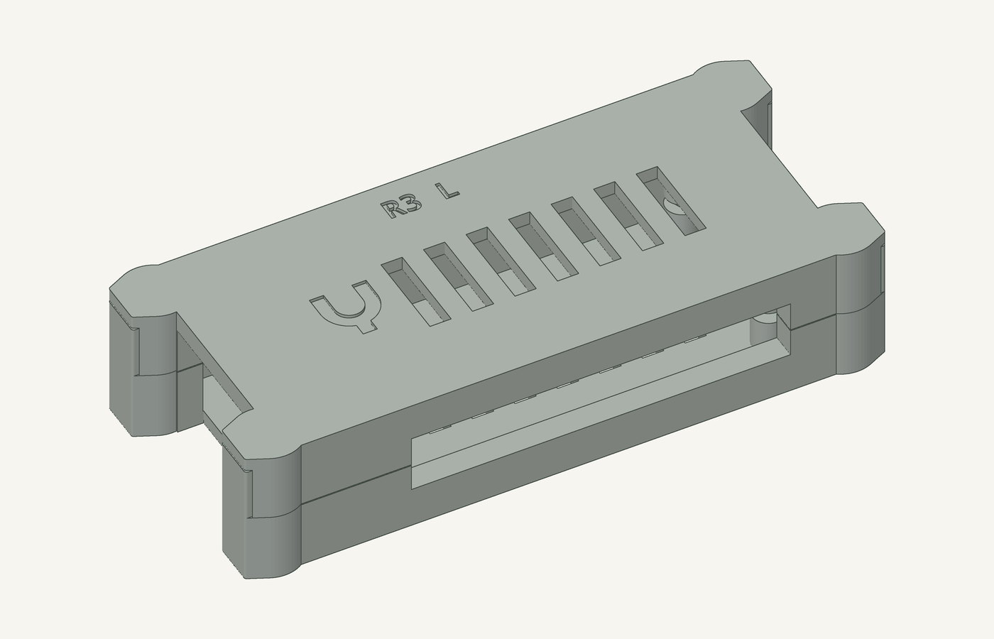
Mechanical revision
| Feature | Nominal design |
|---|---|
| Central body / maximum ear envelope | 79.6 × 38 × 20 / 90.4 × 39.6 × 20 mm |
| Internal cavity, official board XY frame | x −7…65.4, y −0.4…30.4 mm |
| PCB top / lower and upper pad faces | z 8.5 / 6.88 and 8.52 mm |
| Head well / bearing plane | Ø5.8 mm / z 2.4 mm |
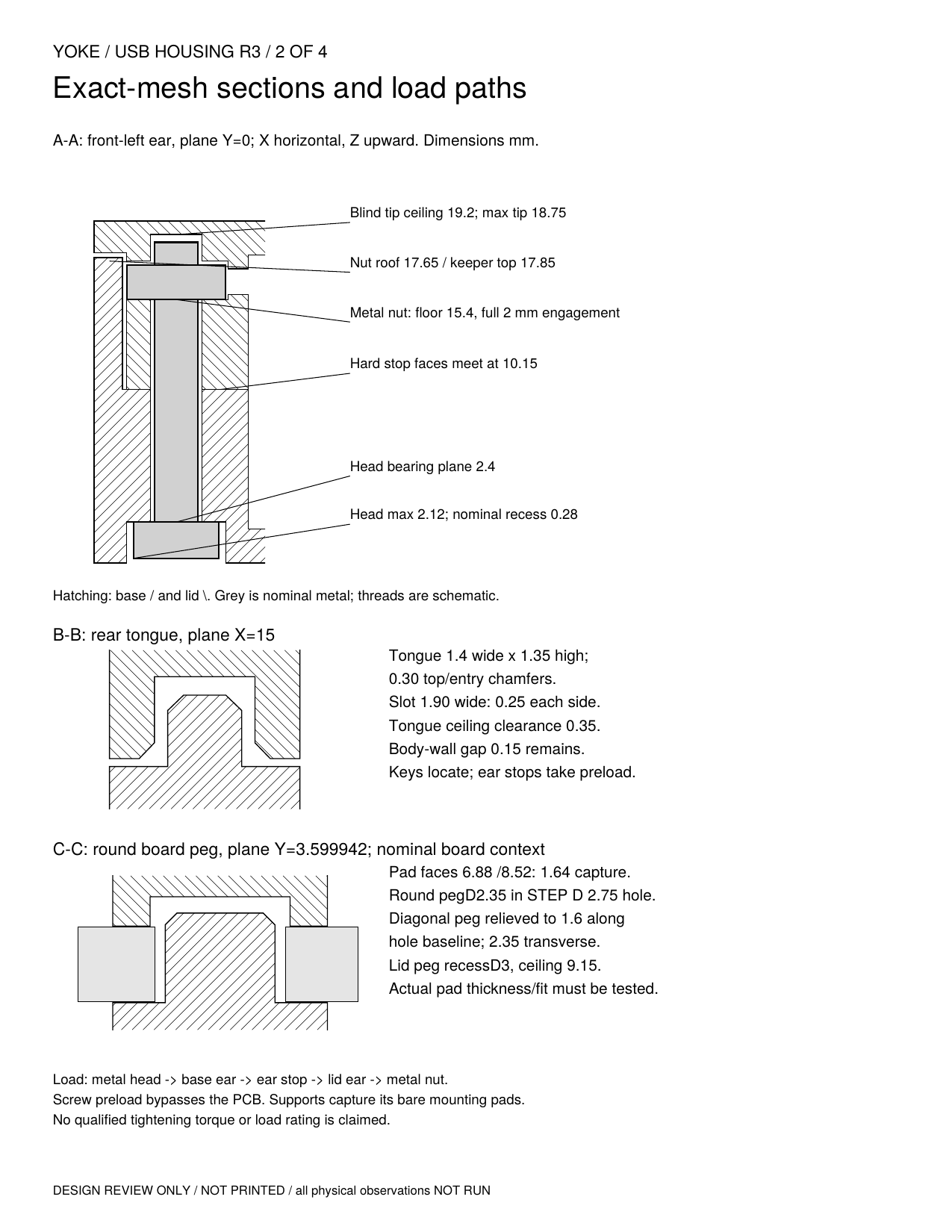
| Nut trap | AF5.25, z 15.4…17.65 mm, side loading |
| Blind screw-tip ceiling | z 19.2 mm; 0.8 mm exterior cap |
| Ear stop faces / body wall gap | z 10.15 mm / 0.15 mm |
| Three tongues | 1.4 mm wide × 1.35 mm high; lengths 8, 10, 10 mm |
| Tongue fit | 0.25 mm per side/end, 0.35 mm ceiling gap, 0.30 mm lead-ins |
| Board locators | Ø2.35 round peg and 2.35 × 1.6 mm relieved diagonal peg |
| Official STEP mounting-hole diameter | 2.75 mm; round-peg radial allowance 0.20 mm |
The end ears keep the case narrow while providing material around the head wells and nut seats. The minimum nominal head-well-to-cavity wall is 1.3 mm; the bearing column above the head seat is 7.75 mm. The Ethernet port cutter acts on the end wall, without cutting the board-support posts. The front cable bay remains clear of the new fastener axes.
The three chamfered tongues register the halves in XY. Ear stops take screw preload while the original pad coordinates provide a nominal 1.64 mm board capture gap. The round peg locates one mounting hole; the second peg is relieved along the diagonal hole-centre line to accommodate centre-distance variation. The lid provides receiving recesses for both pegs. Actual board thickness and fit remain unmeasured; screws must never pull an interfering board into position.
Each nut slides into a roofed trap from the outboard end of the lid. Integral base fingers close those exits when the halves seat. The nuts then remain captive even with the screws removed. Keep the lid level over a tray during opening: the exits reopen before the lid is fully detached. A blunt 1.2 mm pin through the inner service hole can push a nut out with the lid removed. No extra keeper part, printed thread, adhesive or heat-set insert is used.
Before fitting the board or screws, test the coupon/empty case over a tray: hold the stops fully seated and gently rotate through six orientations. Require all nuts retained and restrained against free rotation, then reopen level to check controlled release. This physical test remains NOT RUN.
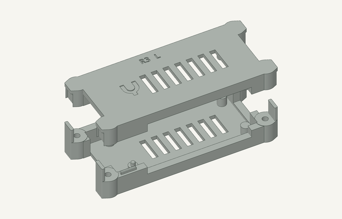
The canonical Yoke mark is imported
directly, recessed 0.45 mm at an 8 mm visible width. Parts carry R3 B and
R3 L identification. The original 3 × 13 mm vents remain open.

Hardware and assembly
Use four M2.5 × 16 mm PH1 pan-head screws and four M2.5 hex nuts. The Accu screw specification gives 16 ± 0.35 mm under-head length, maximum Ø5 × 2.12 mm head and 0.45 mm pitch. The manufacturer DIN 934 table gives M2.5 nut thickness 1.75–2.00 mm, AF5 and minimum corners 5.45 mm. Measure the actual supplied hardware before use.
The four-page assembly and test PDF includes exact-mesh sections, nut loading, hardware inventory, closure and reverse service. Both halves print outside-face down. Each manufactured half contains four 0.20 mm sacrificial bore membranes: eight cleanup holes total.
Hand-clear with a 3 mm, 118° twist bit whose point is at most 1.0 mm long, using a physical depth stop. Enter from the mating ear face: base tip depth 9.0 mm toward the open head well; lid tip depth 6.5 mm toward the nut trap. These depths include the drill point. Do not drill through the exterior lid cap or use a power drill. Support the broad body on wood blocks, leaving the tall keeper fingers free of drilling loads. Keep the board away and remove all swarf. Require eight clear 3.0–3.2 mm bores and intact seats/caps.
The PDF defines measured stack checks before assembly: at least 0.30 mm tip-to-ceiling clearance, 0.45 mm of screw beyond the nut and 0.15 mm of head recess. Nominal worst specified hardware gives 0.45, 0.65 and 0.28 mm, respectively. Those numbers do not include print error; measured failure requires a revised stack, not extra tightening.
Files and rebuilding
- housing.scad: standalone native parametric CAD. Select
base,base-printed,lid,lid-printed,lid-assembled,plate,assembled,exploded, the fourcoupon-*variants,screwornut. - base.stl / lid.stl: finished parts. The lid uses its
inverted print frame; assembly transform is
(x, 30−y, 20−z). - base-printed.stl / lid-printed.stl: manufactured parts with the removable membranes.
- yoke-usb-housing-r3.stl: two-part main plate.
- yoke-usb-housing-r3-coupon.stl: separate
two-part fit coupon, cut from the actual front-left corner. It includes
the head well, nut trap, keeper, front tongue and round board peg. Use one
of the same screws/nuts and clear its two membranes.
CB/CLidentify its halves. It does not establish full-board fit or strength. - The companion
.contact.jsonfiles declare exact placed components and prototype bridge allowances; they are not print releases. - validation.json: concise hashes and nominal check results.
From the repository root, using Manifold-enabled OpenSCAD (verified with 2026.09.19):
python3 hardware/usb-housing/r3/build.py
python3 hardware/usb-housing/r3/build.py --output .scratch/housing-r3-author/rebuild
The build requires only the standard library and OpenSCAD and preserves the
individual facets when packing plates. To regenerate the PDF and exact-mesh
images, use --documents in a Python environment with numpy, trimesh,
Pillow and reportlab, plus pdftoppm. Documentation transients stay under
the repository’s .scratch/housing-r3-author/ directory.
Checks and limits
The nominal checks cover watertight parts, reproducible outputs, assembled base/lid and metal-envelope clearance, sampled lid/nut/screw insertion, closed keeper obstruction and conservative official-board component bounds. The normal Lacuna mesh preflight passes both main and coupon plates with supports disabled, including bed-contact and layer-support checks. All exported facets exceed its zero-area threshold. These checks do not constitute a print release. The vendor board mesh is nonmanifold; it is not a Boolean collision proof, and samples do not establish continuous collision-free movement.
The owner reports that assembly failed. The specific failure mechanism and dimensions have not been recorded. The remaining prescribed fit measurements, cable checks, 5 N retention and 30-minute thermal tests remain NOT RUN. The model targets the bare board, with USB-C overmoulds no larger than 12 × 7 mm. No PoE HAT, added heatsink, bracket, ingress rating or qualified tightening torque is included. Follow the PDF’s measurements, test limits and stop conditions.
R3 changes the mechanics and screw length. No R1/R2 approval carries over. The main plate passed exact-file assembly/manufacturing review and release before its single recorded dispatch. The coupon has not been sliced or dispatched. The PDF retains its design-stage preparation status; the dispatch record records the later print. Any subsequent print needs its own reviewed exact job, release and authorization for a clear bed.