
R4 compact housing — design review
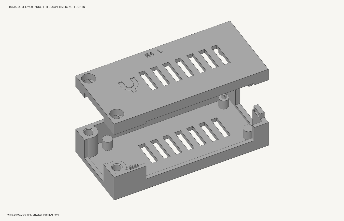
R4 replaces the two rejected housing prints. It keeps the loaded ZERO 3E inside one flat 76.8 × 35.9 × 20.0 mm rectangle, with no external ears or towers. It uses two M3 × 8 socket-head screws and two RX-M3×5.7 heat-set inserts. The lid slots together and screws together: lower it 1.2 mm left of its final position, slide it right into three guides and two rear retaining pockets, then install the recessed screws.
Do not print the full case yet. The catalogue dimensions are known, but matching the owner's actual insert stock, measured screw dimensions, coupon fit and physical assembly remain unverified. Start with a small set of joint samples to test the nominal design. Match the actual inserts to the listed part before heat setting. The coupon job needs its own exact-job review; it does not release the full case.
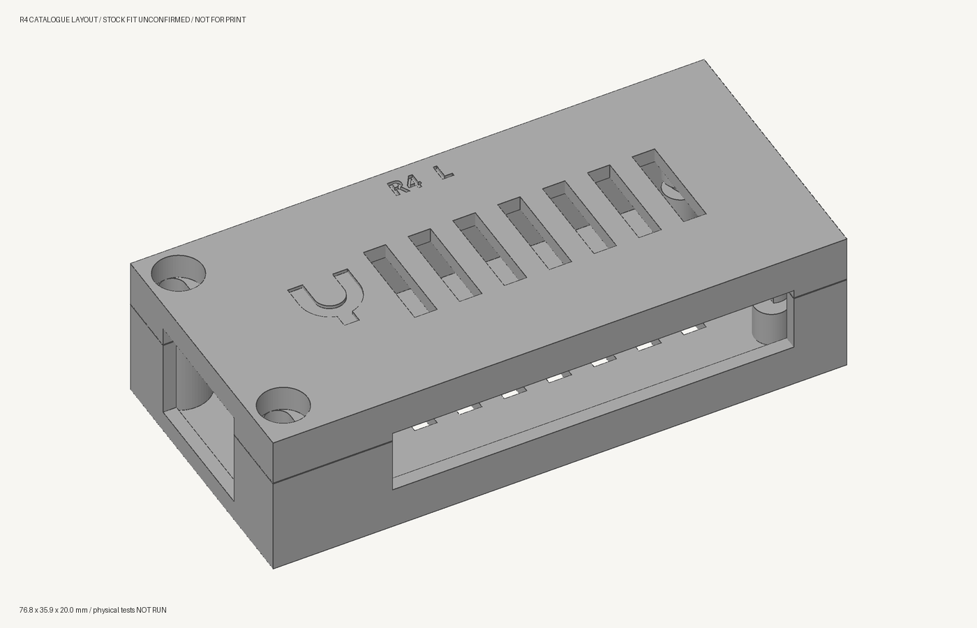
Compact envelope and actual board
The official loaded-board reference occupies x −6.4…65.00165, y −1.5…30.00553 mm. R4 occupies x −9.2…67.6, y −3.7…32.2 mm; the extra space supplies the wall, connector clearance and internal fastener material. It does not put a large bolt margin around the PCB. The two fasteners sit in the otherwise unused corners beside the RJ45 connector, at (−5, 1.6) and (−5, 28) mm. No M3 screw passes through the PCB's original Ø2.75 mm holes.
The original four support positions and two relieved locating pegs remain. PCB lower pad / upper pad faces are nominal z 6.88 / 8.52 mm. The lid's capture faces are z 8.70 mm, giving 0.18 mm pad play; the case's hard stops carry screw preload. Tightening must never pull an interfering PCB into place. Bare board only: no PoE HAT, added heatsink or bracket is included.
Hardware profile and load path
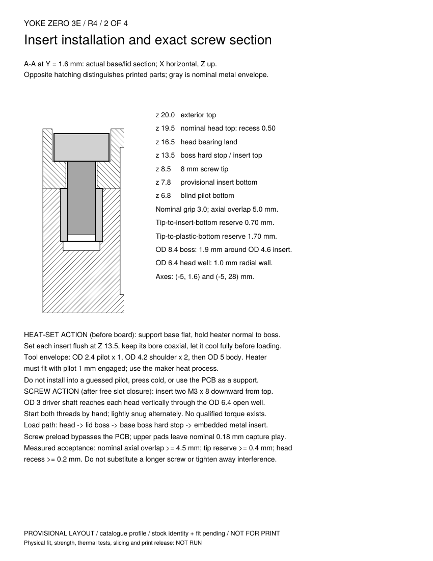
hardware.json distinguishes catalogue facts from unconfirmed stock. The Ruthex product page and manufacturer RX-series datasheet identify RX-M3×5.7 as Ø4.6 × 5.7 mm, lead-in Ø3.9, recommended pilot Ø4.0, minimum surrounding wall 1.6 mm (product GE-M3x57-001, EAN 4260528721146). The nominal boss has 1.9 mm surrounding wall. Pilot depth 6.7 mm is our design allowance of insert length + 1.0 mm, not a quoted manufacturer requirement. Actual insertion fit remains a coupon question.
The FGRUH M3 kit contains the selected M3 × 8 length; one reported sample head height is 2.9 mm. The CAD's Ø6 × 3 mm head is an envelope assumption, not measured stock tolerances. No Lacuna stock reservation is claimed.
| Interface | Nominal design |
|---|---|
| Boss OD / head well | 8.4 / 6.4 mm |
| Hard stop / insert top | z 13.5 mm |
| Head bearing plane / nominal head top | z 16.5 / 19.5 mm |
| 8 mm screw tip / insert bottom / pilot bottom | z 8.5 / 7.8 / 6.8 mm |
| Plastic grip / axial metal overlap | 3.0 / 5.0 mm |
| Insert-end / plastic-bottom tip reserve | 0.70 / 1.70 mm |
| Nominal head recess | 0.50 mm |
| Three guide tongues | 1.0 mm wide × 1.2 mm high |
| Guide slot side allowance / real wall each side | 0.25 / 0.85 mm |
| Rear tab underlap / root / toe thickness | 0.75 / 1.0 / 0.5 mm |
| Rear pocket / tab width | 4.4 / 3.9 mm |
| Rear pocket side / matching-face vertical allowance | 0.25 / 0.30 mm |
| Receiver roof / remaining rear wall | at least 1.5 / 1.2 mm |
Two flat bearing shelves support each screw head. A 3.4 mm X × 6.4 mm Y capsule passage permits those shelves to print as bridges while leaving an open shank passage. Its narrow X direction provides a positive reverse-slide stop with the M3 screw installed. There are zero sacrificial bore skins. Both parts print exterior-face down. The insert pilots are open from the mating side and accessible before the board is installed.
The clamp path is head → lid boss → base boss hard stop → embedded insert; it bypasses the PCB. Rear matched sloping faces carry opening load into the receiver, while front screws restrain reverse X travel. Guide walls carry XY location. Smooth metal meshes establish nominal axial overlap, not measured usable thread engagement, torque capacity or insert pullout strength.
Build and service instructions
For the small joint-test print, use the separate coupon assembly and test instructions. They list only the five printed samples, one screw and one insert.
The four-page full-case assembly and test packet covers the inventory, insert/tool access, exact joint sections, board insertion, lower-and-slide closure, screw installation, reverse service, and the first physical tests. All physical observations remain NOT RUN.
Set inserts in the empty base, flush with its boss faces; cool them before loading. The declared heater envelope is a Ø2.4 × 1 mm pilot, Ø4.2 × 2 mm shoulder, and Ø5 mm body above it. The actual heater must fit that envelope; use the insert maker's process instructions. The Ø3 mm driver shaft has straight access through each head well.
Lower the lid level at −1.2 X, then slide +1.2 X until the outer faces align. It must seat freely before screws are fitted. Start both M3 × 8 screws by hand and lightly snug alternately; no qualified torque is specified. For service, disconnect all cables, remove both screws, slide −1.2 X, then lift. Do not try to lift the engaged rear hooks straight upward.
Small first-article coupons
The native CAD crops the actual front screw/guide and rear retaining joint; it does not substitute a generic insert block. The five-part set is about 6.47 cm³ of model material, before any slicer additions:
front-base+front-lid: actual insert boss, head shelves, driver access, guide, stop height and screw reach. The base crop extends beyond the lid to expose a floor ledge for the clamp. Use one M3 × 8 screw and one RX insert.rear-base+rear-lid: actual hook and roof/pocket section.rear-jig: a separate bench fixture whose hard X faces substitute for the full case's front-screw restraint during the rear-joint load trial.
Close the rear pair outside the jig, then lower the closed pair onto its 2 mm floor. Hard faces at X 55.5 / 67.7 permit at most 0.2 mm relative reverse travel. Its tall stop wall is 5.0 mm thick. A simple cantilever estimate for the earlier 3 mm wall exceeded the 0.1 mm deflection limit; the thicker wall reduces that risk but still needs measurement. First check that the closed pair moves vertically with less than 0.5 N drag while holding the jig floor. Then clamp the lower sample and jig floors together to a supporting bench through the rear window, leaving the lid free. Holding only the jig would let both samples lift together and would not test retention. Require loaded stop deflection ≤0.1 mm and relative X travel ≤0.3 mm, or invalidate the fixture result. Apply the declared upward +Z test load under the exposed lid roof edge at Y 9.1, clear of its internal pad. The packet specifies 5 N for 10 s, three times, and ten assembly/service cycles. Record actual screw turns, dimensions, forces, gaps and damage. Coupon results do not prove full-board/cable/thermal fit.
Rebuild and check
housing.scad is native parametric CAD. build.py
exports source-matched parts and packs unchanged component facets onto full
and coupon layout plates. Normal export refuses the unconfirmed stock profile;
--provisional confines its engineering meshes to this repository's .scratch.
Only selected review images/PDF are committed; no R4 print STL or G-code is
published.
--coupon-trial prepares the nominal joint-test plate while keeping actual
stock fit unconfirmed. It marks only the coupon plate for that test; the
full-case plate remains a layout artifact. The exact coupon job still needs
Lacuna's assembly release and owner authorization before dispatch.
With Manifold-enabled OpenSCAD (used here: 2026.09.19):
python3 hardware/usb-housing/r4/build.py --provisional \
  --output .scratch/usb-housing-r4

python3 hardware/usb-housing/r4/build.py --coupon-trial \
  --output .scratch/usb-housing-r4-joints
For check.py, render.py and document.py,
use Python with numpy, trimesh, scipy, networkx, manifold3d, Pillow and reportlab.
pdftoppm is also required for the PDF page images. The Lacuna checkout supplies
the normal mesh and sampled-geometry tools. Reproduce with explicit inputs:
python hardware/usb-housing/r4/check.py \
  --output .scratch/usb-housing-r4 \
  --board-mesh /path/to/exact-reference/board.stl --lacuna ../lacuna
python hardware/usb-housing/r4/document.py \
  --output .scratch/usb-housing-r4
To rebuild the board reference, obtain rs109_pcba.stp from Radxa's
official ZERO 3E STEP archive,
also linked from Radxa's downloads.
The URL can change; these SHA-256 hashes pin the reviewed content:
| Input | SHA-256 |
|---|---|
| ZIP | 616fb4e1017a3ca7a1025372ccc018520a7ccd2ba614e2d6454f0782279f6645 |
rs109_pcba.stp |
97b0a1100cb7cb1e0fbd5aed50f8d6b0422b8885580f937163bdd119ceaab4ca |
Generated board.stl |
1c1268c8af4b1a6c0b07fec07b3b28c6662e5d10c0c1b794c1f1083f31af8f27 |
reference.py reproduces the original tessellation. The verified
environment was Python 3.14.9, CadQuery 2.8.0, cadquery-ocp 7.9.3.1.1 and
OCCT 7.9.3. Install those CAD packages in a separate development environment;
they are not Yoke runtime dependencies. After extracting the STEP under
.scratch, run:
python hardware/usb-housing/r4/reference.py \
  --step .scratch/radxa/rs109_pcba.stp \
  --output .scratch/usb-housing-r4-reference/board.stl
The exporter uses relative deflection 0.05 and angular tolerance 0.1, binary
STL, relative=True and parallel=True. It verifies both input and output
hashes. The unchanged source frame receives +8.5 Z in the assembly checker.
Use the resulting path as --board-mesh above. Another tessellation requires
a deliberate reference/hash review; it is not silently interchangeable.
Neither generator nor checker depends on a hidden R3-cache path.
Evidence and limits
validation.json records concise exact-input identities and nominal results. The earlier independent mechanical review and review result cover the case and original joint samples. The current coupon job separately reviews the larger front clamp ledge, thicker jig and lower-sample hold-down. Both layout plates pass the normal Lacuna mesh preflight with supports disabled; no zero-area facets remain. Actual base/lid/tool/hardware paths have no sampled collisions. Each promised guide survives export with both 0.85 mm walls. The official board is nonmanifold, so its separate actual surface-edge check supplements the sampled solid checker; those samples show zero transverse crossings through closure and service.
The initial layout's digital failures caused native geometry changes: the rear-port roof was opened through the base rim; annular head-well cantilevers became bridge shelves; receiver end walls and matched lip chamfers supply print support; an eliminated front guide moved clear of its port; all guide slots gained actual surrounding material. The first slide also collided with a USB-C shell, so its front-right upper support was relieved. These were consequential design findings, not threshold overrides.
Samples cannot prove continuous paths or exclude face-only/containment collisions. The declared bridge span is nominal engineering judgement until a physical coupon tests it. Cable engagement, actual insert fit, useful thread engagement, strength, assembly cycles and 30-minute thermal observation remain NOT RUN. The conservative 75 °C prototype stop is a trial limit, not a component rating. Independent design review does not replace Lacuna's fresh exact-job assembly release, toolpath checks or physical observations.